
Unsprung Mass Dynamics and Suspension System Challenges
The primary engineering challenge associated with in-wheel motor integration is the substantial increase in unsprung mass ( ). In a conventional vehicle architecture, the motor, transmission, and differential are supported by the vehicle suspension springs, constituting sprung mass. Housing the motor, electromagnetic braking hardware, and cooling jackets directly inside the wheel assembly increases individual corner mass from a baseline of
 to
 (
 to
 ).
This elevated unsprung mass alters vehicle ride and handling characteristics by shifting the wheel hop natural frequency ( ), which is governed by the relation:
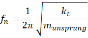
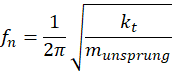
where  represents the vertical tire stiffness coefficient. Increased unsprung mass amplifies dynamic tire load variations when traversing road irregularities, reducing tire contact patch adhesion and degrading high-frequency ride comfort.
Mitigating these dynamic penalties requires advanced suspension engineering, including semi-active magnetorheological dampers with rapid damping force adjustment rates ( ) and lightweight composite wheel rim materials that minimize rotational inertia.
Independent Wheel Traction and Tire-Road Adhesion Mechanics
Distributed drive architectures decouple tractive force generation across all four wheels, permitting independent control over tractive ( ) and braking (
 ) forces at each contact patch. The longitudinal force generated by each in-wheel motor depends directly on the normal load (
 ), tire slip ratio (
 ), and the dynamic friction coefficient (
 ) defined by the Magic Formula tire model:


where  and
 represent empirically derived tire stiffness, shape, peak, and curvature coefficients.
During acceleration on heterogeneous road surfaces exhibiting split-friction coefficients (such as ice on one side and dry asphalt on the other), traditional mechanical limited-slip differentials experience transmission delay and slip oscillations. In-wheel torque vectoring controllers detect wheel-speed differentials within  via high-resolution resolver sensors, instantly reducing torque on the slipping wheel while redirecting electrical power to the opposing wheel maintaining high traction. This instantaneous redistribution prevents wheel spin, maximizes longitudinal acceleration, and maintains vehicle directional control without requiring mechanical locking mechanisms.
Torque Vectoring Algorithms and Yaw Rate Control
Navigating high-speed cornering maneuvers introduces lateral acceleration and centrifugal forces that induce understeer or oversteer tendencies. In-wheel electric motor torque vectoring control neutralizes these handling instabilities by generating an active direct yaw moment ( ) around the vehicle center of gravity:
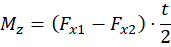
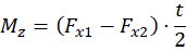
where  and
 represent the longitudinal tractive forces of the outer and inner wheels, and
 denotes the vehicle track width.
Advanced vehicle dynamics controllers utilize Model Predictive Control (MPC) and sliding mode control algorithms to compute optimal yaw rate tracking errors. When a vehicle exhibits understeer during sharp cornering, the control algorithm commands positive torque vectoring—delivering higher tractive force to the outer wheels while applying regenerative braking torque to the inner wheels. This differential force vector creates an assisting yaw moment that pivots the vehicle chassis into the turn, reducing steering wheel angle input requirements and enhancing cornering trajectory tracking accuracy.
Technical Data Specifications of In-Wheel Drive Parameters
| Powertrain & Dynamics Parameter | Engineering Specification Range |
|---|---|
| Individual In-Wheel Motor Power |  to  per motor (  ) |
| Peak Torque Output per Wheel |  to  (  ) |
| In-Wheel Motor Mass Penalty |  to  per corner (  ) |
| Torque Vectoring Response Latency |  to  closed-loop command execution |
| Regenerative Braking Power Limit | Up to 80% total kinetic energy recovery capacity |
| Inverter Switching Frequency |  to  wide-bandgap  inverters |
| Operating Rotor Speed Range |  to  direct or planetary reduction |
Regenerative Braking Integration and Energy Recovery
Decentralized in-wheel motor drive systems optimize energy recovery by replacing traditional friction-based foundation brakes with independent electric regenerative braking across all four wheels. When the driver depresses the brake pedal, the vehicle control unit calculates the total deceleration demand and distributes braking torque dynamically.
Unlike centralized electric powertrains where regenerative braking acts primarily on the driven axle, in-wheel architectures apply negative torque independently across four quadrants. This enables complete regenerative control over anti-lock braking (ABS) and electronic stability control (ESC) routines.
Regenerative braking torque generated by permanent-magnet synchronous motors converts vehicle kinetic energy back into electrical energy with round-trip conversion efficiencies exceeding 85%. The generated multi-phase AC power is rectified by wide-bandgap silicon carbide ( ) inverters and routed back into the high-voltage lithium-ion battery pack. Integrating friction brake blending algorithms ensures that mechanical disc brakes engage only during emergency hard stops or when the battery reaches 100% state-of-charge, maximizing total urban driving range.
Thermal Management and Electromagnetic Shielding
Operating permanent-magnet motors within confined wheel rim enclosures exposes internal electromagnetic windings and inverter electronics to severe thermal loads, mechanical shock, and environmental contamination. Continuous high-torque hill climbing or aggressive track driving generates massive stator copper losses ( ) and rotor eddy current heating.
Thermal management engineering requires integrating internal cooling jackets circulated with a water-glycol coolant pumped through hollow suspension control arms directly into the wheel hub. Maintaining stator winding temperatures below  (
 ) prevents thermal demagnetization of neodymium-iron-boron (
 ) permanent magnets. Furthermore, robust electromagnetic compatibility (EMC) shielding prevents high-frequency inverter switching noise from interfering with vehicle radar sensors, CAN bus communications, and GNSS navigation modules.
The Final Take
Mastering in-wheel electric motor torque vectoring control redefines vehicle dynamics, traction management, and regenerative energy recovery. Citing International Energy Agency mobility assessments and automotive engineering research, decentralized multi-motor drive configurations eliminate mechanical transmission losses while delivering millisecond-precision yaw rate control and stability augmentation. By balancing unsprung mass penalties with advanced torque vectoring algorithms, distributed in-wheel drive systems establish an inspiring technical foundation for high-efficiency electric vehicles.

Comments (0)
Login to leave a comment.
No comments yet. Be the first to share your thoughts!