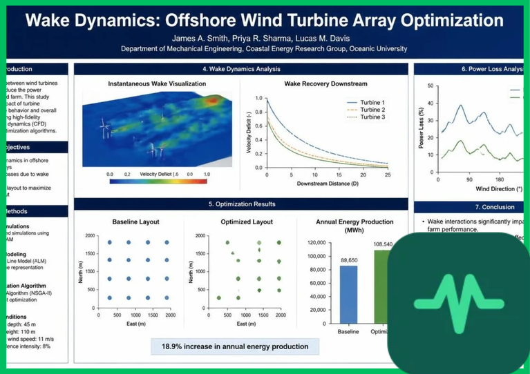
Aerodynamic Wake Physics and Velocity Deficit
The foundational physics of wind turbine wakes stem from momentum conservation and thrust extraction across the rotor disc. As air flows through the rotor sweep area, the axial force exerted on the wind creates a pressure drop, quantified by the thrust coefficient ( ). The magnitude of the initial velocity reduction depends on the operating tip-speed ratio (
 ) and blade pitch angle.
Immediately behind the rotor plane, the near wake region exhibits complex tip vortices, root vortices, and pressure recovery dynamics. Within 2 to 4 rotor diameters ( ), the flow transitions into the far wake region, where turbulent mixing entrains higher-momentum air from the surrounding atmospheric boundary layer back into the wake core. The downstream wind velocity (
 ) at distance
 is modeled using empirical wake deficit formulations such as the Jensen wake model:


where  represents free-stream wind speed,
 is the rotor diameter, and
 denotes the wake decay constant (typically
 to
 for offshore marine atmospheric boundary layers). Unmitigated wake deficits reduce downstream turbine wind speeds by 20% to 40%, resulting in cumulative annual energy production (AEP) losses ranging from 5% to 15% across large offshore wind arrays.
Turbulence Intensity Modeling and Atmospheric Boundary Layer
Atmospheric stability and ambient turbulence intensity ( ) dictate how rapidly downstream wakes recover their kinetic energy. Over marine environments, atmospheric boundary layers alternate between stable, neutral, and unstable stratification conditions based on air-sea temperature differentials.
Under highly stable atmospheric conditions—common in marine environments when warm air flows over colder sea surface temperatures—low ambient turbulence ( ) suppresses vertical momentum mixing. Under these conditions, wakes persist over long downwind distances, severely impacting downstream turbine performance. Conversely, unstable atmospheric stratification enhances convective mixing and accelerates wake recovery.
Turbulence intensity modeling within wind farm layout software incorporates ambient turbulence alongside added turbulence generated by upstream rotor blades. This added turbulence intensity ( ) scales with thrust coefficient and downstream distance, increasing mechanical fatigue loads on structural components, including tower foundations, drive trains, and composite blades. Excessive cyclic turbulence accelerates material degradation, increasing operational and maintenance (O&M) expenditures for offshore assets.
Active Wake Mitigation and Yaw Misalignment Steering
Mitigating downstream velocity deficits has shifted from passive geometric spacing—widening turbine layouts to reduce wake overlap—to active aerodynamic control strategies. Active wake steering utilizes yaw misalignment to intentionally deflect the trailing wake away from downstream turbines.
By rotating the nacelle of an upstream turbine at a controlled yaw angle ( , typically
 to
 ) relative to the incoming wind vector, the thrust force vector decomposes laterally. This lateral force generates a curved, rolling vortex pair (counter-rotating vortices) that displaces the low-velocity wake core horizontally out of alignment with downstream rotor disks. While the upstream turbine experiences a minor power reduction due to its yawed orientation, the aggregate power yield of the downstream turbine increases significantly, boosting total wind farm array efficiency by 2% to 5%.
Advanced control architectures also employ active axial induction control. By dynamically pitching rotor blades or adjusting generator torque to vary the thrust coefficient during high-wind intervals, upstream turbines intentionally shed less kinetic energy locally, allowing higher momentum flux to reach downstream assets.
Technical Data Specifications of Offshore Wind Wake Parameters
| Wind Farm & Wake Parameter | Engineering Specification Range |
|---|---|
Rotor Diameter ( ) |  to  (  to  ) |
| Turbine Nameplate Capacity |  to  (  ) |
Jensen Wake Decay Constant ( ) |  to  (offshore marine boundary layer) |
Ambient Turbulence Intensity ( ) | 3% to 10% marine atmospheric conditions |
Optimal Yaw Misalignment Angle ( ) |  to  for active wake steering |
| Cumulative AEP Wake Loss Factor | 5% to 15% annual net energy production reduction |
| Downstream Wake Recovery Distance |  to  (  to  [  ]) |
Computational Fluid Dynamics and Array Optimization
Designing high-efficiency offshore wind arrays requires sophisticated computational fluid dynamics (CFD) simulation engines and analytical frameworks such as the FLORIS (Farm Flow Simulation and Steering) toolset. These engineering models solve Reynolds-Averaged Navier-Stokes (RANS) equations coupled with advanced turbulence closures (such as the  -epsilon or
 -omega shear-stress transport models) to predict three-dimensional wind velocity vectors across multi-gigawatt leasing zones.
Array optimization algorithms integrate metocean data—including wind rose frequency distributions, directional wave spectra, and tidal currents—to determine optimal turbine micro-siting coordinates. By accounting for prevailing wind directions and dynamic wake interactions during layout design, developers minimize wake overlap, reduce structural fatigue, and maximize capital expenditure returns over a 25-year operational lifecycle.
The Final Take
Optimizing offshore wind turbine aerodynamic wake mitigation establishes an essential technical foundation for utility-scale marine renewable energy deployment. Citing International Energy Agency offshore wind assessments and academic fluid dynamics literature, mastering wake steering controls, turbulence modeling, and CFD array optimization recovers lost kinetic energy and maximizes annual energy production. By mitigating velocity deficits across massive offshore wind farms, advanced aerodynamic control secures high-efficiency renewable power generation for global electricity grids.

Comments (0)
Login to leave a comment.
No comments yet. Be the first to share your thoughts!