
In contrast, bifacial photovoltaic modules feature transparent front and rear contacts, enabling the absorption of both direct solar radiation from the front side and reflected diffuse radiation (albedo) from the underlying ground surface on the rear side. Maximizing bifacial energy yield requires rigorous engineering control over ground surface albedo coefficients, mounting structure height, module tilt angles, row spacing geometry, and rear-side mismatch losses caused by shading and electrical interconnection architectures.
Ground Albedo Physics and Surface Reflectance Coefficients
The foundational physical factor determining bifacial energy gain is the ground surface albedo ( ), which quantifies the ratio of reflected shortwave radiation to incident global horizontal irradiance (
 ) striking the terrain beneath and surrounding the photovoltaic array. Albedo varies significantly depending on geological material composition, moisture content, vegetation cover, and snow accumulation:
- Fresh Snow Cover: Exhibits the highest natural albedo coefficient, ranging from 0.70 to 0.90 (
 to
 solar reflection), generating massive rear-side irradiance enhancements.
- Concrete and Light-Colored Aggregate: Renders high albedo values between 0.35 and 0.50 (
 to
 reflectance), frequently utilized in commercial rooftop or desert industrial installations.
- Dry Desert Sand and Light Soils: Yields moderate albedo metrics ranging from 0.25 to 0.40 (
 to
 reflection).
- Green Grass and Vegetative Cover: Exhibits lower albedo values between 0.15 and 0.25 (
 to
 reflectance).
- Asphalt and Dark Organic Soil: Renders minimal albedo coefficients between 0.05 and 0.15 (
 to
 reflection), resulting in low rear-side energy capture unless artificial reflective ground covers (geotextiles) are installed.
Quantifying total rear-side irradiance ( ) requires modeling the view factor (
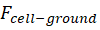 ), which calculates the geometric proportion of radiation emitted from the finite ground area that intercepts the rear surface of the elevated photovoltaic module string.
Bifaciality Factor and Cell Architecture Mechanics
The internal electrical conversion efficiency of the rear-side active layer is governed by the module bifaciality factor ( ), defined as the ratio of rear-side power conversion efficiency (
 ) to front-side power conversion efficiency (
 ) under standard test conditions:
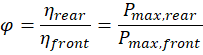
State-of-the-art passivated emitter and rear contact (PERC) bifacial modules achieve bifaciality factors ranging from 65% to 75%, whereas high-performance n-type tunnel oxide passivated contact (TOPCon) and heterojunction (HJT) solar modules attain superior bifaciality factors between 80% and 95%.
Achieving high bifaciality requires optimizing cell architecture to eliminate rear-side metallization shading. Monofacial cells incorporate full-area aluminum back-surface fields ( ) that block rear illumination entirely. Bifacial cells replace solid aluminum rear contacts with localized screen-printed silver grid fingers or transparent conductive oxide (TCO) layers, allowing long-wavelength photons (
 to
 ) to penetrate and generate electron-hole pairs within the base silicon substrate regardless of whether light enters from the front or rear surface.
Mounting Geometry, Ground Clearance, and View Factor Optimization
Optimizing rear-side energy yield requires engineering the physical geometry of the mounting structure. Because rear-side irradiance is highly dependent on ground-reflected light distribution, structural parameters such as installation height ( ), row pitch (
 ), and module tilt angle (
 ) dictate the uniformity of the rear-side illumination profile.
Increasing ground clearance height—elevating the lower edge of tracker-mounted or fixed-tilt modules from a baseline of  to
 (
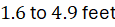 ) up to
 (
 )—widens the ground view factor, exposing the entire rear surface to a broader expanse of reflected radiation and eliminating edge-shading gradients caused by mounting torque tubes and electrical junction boxes.
Furthermore, single-axis tracker architectures integrated with bifacial modules optimize daily energy yield by continuously adjusting tilt angles ( ). Backtracking algorithms prevent inter-row self-shading during early morning and late afternoon hours, ensuring uniform rear-side irradiance across all panel strings.
Technical Data Specifications of Bifacial Photovoltaic Parameters
| Bifacial & Geometrical Parameter | Engineering Specification Standard |
|---|---|
Bifaciality Factor ( ) | 65% to 75% (PERC); 80% to 95% (TOPCon / HJT) |
Ground Albedo Coefficient ( ) | 0.15 (vegetation) to 0.85 (fresh snow) surface reflectance |
| Bifacial Gain Energy Enhancement | 8% to 25% annual kilowatt-hour yield increase |
Module Ground Clearance Height ( ) |  to  (  ) bottom edge height |
| Single-Axis Tracker Rotation Range |  to  tracking sweep angle |
| Operating Cell Temperature Coeff. | 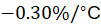 to 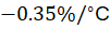 power temperature loss |
| Rear-Side Irradiance Mismatch Limit |  string current variance across module rows |
Electrical Mismatch Losses and Inverter Loading Ratios
While bifacial photovoltaic modules deliver substantial energy yield enhancements, harvesting high rear-side current requires managing electrical mismatch losses within string and inverter architectures. Because ground-reflected irradiance varies spatially across the array—with modules positioned at the outer edges of tracker rows receiving higher rear illumination than interior modules—string currents ( ) diverge.
If string-level current mismatch exceeds system design thresholds, series-connected photovoltaic strings experience clipping losses governed by the weakest illuminated cell. Electrical engineers mitigate mismatch by utilizing multi-MPPT (Maximum Power Point Tracking) string inverters and optimizing DC-to-AC inverter loading ratios (ILR). Because bifacial modules generate peak DC power outputs that exceed nameplate ratings during high-albedo intervals (such as midday snow reflection), oversizing inverter DC capacity relative to AC nameplate rating (ILR ratios of  to
 ) prevents clipping losses while maximizing annual energy harvest.
The Final Take
Mastering bifacial photovoltaic module albedo gain optimization redefines utility-scale solar engineering by capturing reflected ground radiation to maximize total energy yield. Citing IEA photovoltaic research and academic renewable energy literature, optimizing ground albedo coefficients, bifaciality factors, mounting clearance heights, and inverter loading ratios elevates annual power generation by up to 25%. By integrating transparent cell architectures with advanced single-axis tracking geometry, bifacial photovoltaic systems establish an indispensable technical foundation for high-efficiency solar power generation.



Comments (0)
Login to leave a comment.
No comments yet. Be the first to share your thoughts!