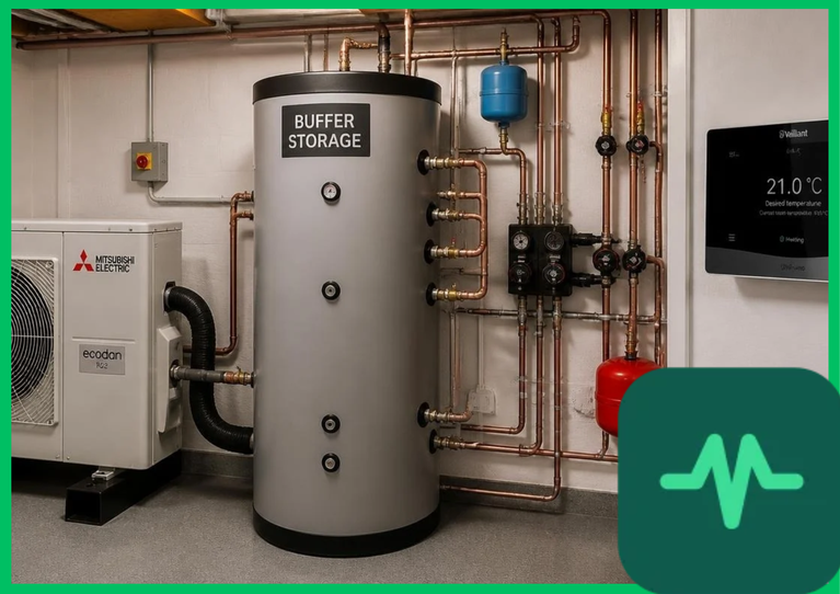
Hydronic Heating Integration and Sensible Heat Stratification
The foundational engineering principle governing buffer tank performance is sensible heat storage utilizing fluid thermal capacity. Water possesses a high specific heat capacity ( [
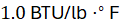 ]), making it an efficient thermal fluid for sensible heat storage tanks ranging from
 to
 (
 ). Energy storage capacity (
 ) is formulated mathematically as:
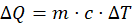
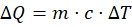
where  represents fluid mass,
 is specific heat capacity, and
 denotes the temperature differential between supply and return loops.
Hydronic heating integration relies heavily on maintaining strict sensible heat stratification within the vertical buffer vessel. Warm supply water entering the upper port of the tank remains segregated from cooler return water entering the lower port due to density differences driven by temperature coefficients ( ). Vertical thermal stratification establishes a sharp thermocline boundary layer, ensuring that the heat pump consistently supplies high-temperature water to the distribution loop while drawing low-temperature fluid from the base, maximizing thermodynamic Carnot efficiency.
Compressor Cycling Reduction and Thermodynamic Efficiency
Operating heat pumps without buffer storage in low-load conditions induces severe short-cycling. Vapor-compression refrigeration cycles require extended stabilization periods (typically 10 to 20 minutes) following compressor startup to achieve steady-state thermodynamic equilibrium, during which refrigerant mass flow rates and expansion valve throttling stabilize. Short-cycling prevents the system from reaching steady-state operation, causing efficiency losses of 15% to 25%.
Buffer tanks absorb excess thermal energy when heat pump output exceeds building thermal demand. Instead of shutting down, the heat pump runs continuously at its optimal part-load modulation ratio (30% to 50% capacity), charging the buffer tank until setpoint temperatures are reached. This continuous operation eliminates electrical starting current surges ( ), protects inverter circuitry, and maintains high seasonal coefficients of performance (
 ).
Technical Data Specifications of Buffer Storage Parameters
| Thermal Storage & Hydronic Parameter | Engineering Specification Standard |
|---|---|
| Buffer Tank Volumetric Capacity |  to  ( 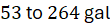 ) residential sizing |
Water Specific Heat Capacity ( ) | 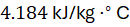 ( 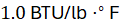 ) sensible storage |
| Thermal Stratification Gradient |  to  (  to  ) vertical thermocline delta |
| Insulation Standby Heat Loss Rate | 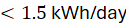 thermal decay threshold (PU foam) |
| Hydronic Loop Temperature Range |  to  (  to  ) radiant/radiator delivery |
| Compressor Minimum Run Time | 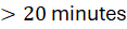 continuous steady-state operation |
| Maximum Operating Pressure Limit |  to  ( 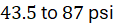 ) ASME pressure rating |
Thermal Mass Optimization and Smart Grid Demand Response
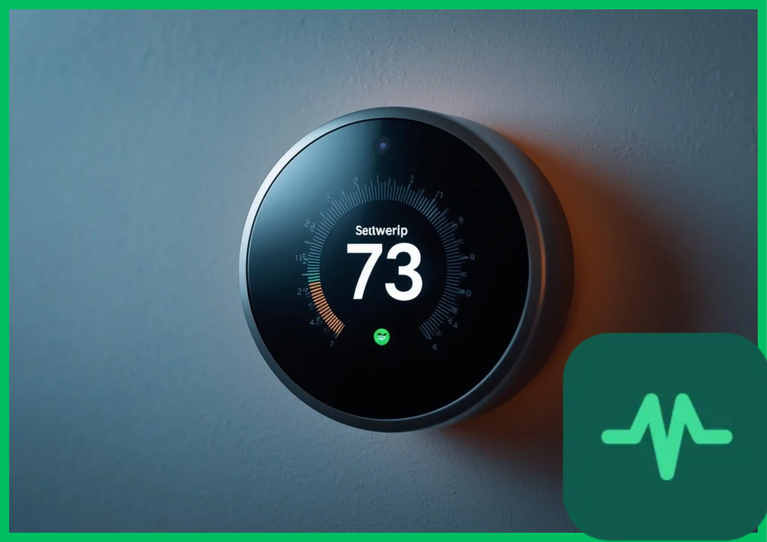
Modern residential energy management systems utilize buffer storage tanks as thermal batteries to execute smart grid demand response and peak load shifting. When electricity tariffs peak or grid carbon intensity surges during morning and evening hours, the heat pump switches off. The building heating loop continues to draw thermal energy stored within the buffer tank, maintaining interior thermal comfort without drawing electrical power from the grid during high-tariff intervals.
Furthermore, thermal mass optimization algorithms compute building thermal time constants and weather forecasts to pre-charge buffer tanks during mid-day hours when photovoltaic generation peaks or electricity prices drop to minimum baselines. Charging storage tanks to elevated supply temperatures ( to
 [
 to
 ]) maximizes stored thermal energy density while maintaining safe mixing valve delivery temperatures (
 to
 [
 to
 ]) for underfloor radiant circuits.
The Final Take
Buffer storage smart home heat pump thermal integration modernizes residential space heating by decoupling generation dynamics from building distribution loads. Citing IEA building decarbonization assessments and ENERGY STAR performance engineering data, integrating stratified sensible heat storage tanks eliminates compressor short-cycling, optimizes part-load coefficients of performance, and enables automated smart grid load shifting. By establishing precise hydraulic decoupling and thermal mass optimization, buffer tanks deliver an indispensable technical foundation for low-carbon residential hydronic heating systems.
Comments (0)
Login to leave a comment.
No comments yet. Be the first to share your thoughts!