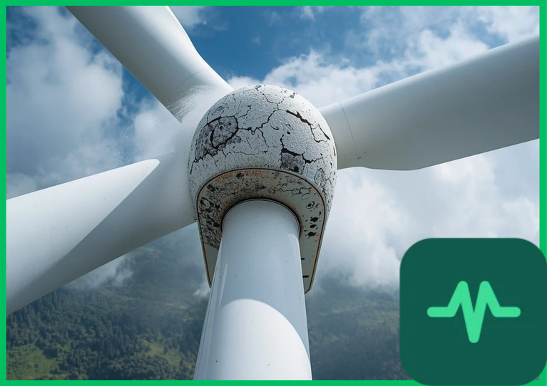
Rain Droplet Impact Physics and Water Hammer Pressures
The primary mechanical mechanism driving leading-edge erosion is high-speed liquid impact stress. Modern utility-scale wind turbines feature rotor diameters exceeding  to
 (
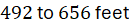 ), generating blade tip speeds (
 ) between
 and
 (
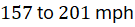 ). When falling raindrops collide with the moving leading edge, the impact velocity generates an instantaneous, high-intensity shock wave known as water hammer pressure (
 ).
The peak water hammer pressure is formulated mathematically as:


where  represents the density of water (
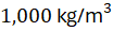 [
 ]),
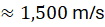
 denotes the acoustic speed of sound in water (
 [
 ]), and
 is the normal impact velocity component. At blade tip speeds of
 (
 ), water hammer pressures exceed
 (
 ) at the microscopic contact point during the initial nanoseconds of impact. This localized hydraulic shock exceeds the ultimate tensile strength and fatigue limit of standard epoxy-glass or carbon-fiber composite matrix materials, initiating micro-pits and subsurface micro-cracks.
Aerodynamic Drag Penalty and Boundary Layer Transition
As leading-edge erosion progresses, surface pitting and coating detachment increase physical surface roughness ( ). Under clean operating conditions, airflow over the front 10% to 20% of the wind turbine blade remains in a smooth laminar boundary layer state, minimizing skin friction drag. Increased surface roughness triggers premature laminar-to-turbulent boundary layer transition. The roughness Reynolds number (
 ) quantifies this transition:
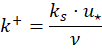
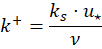
where  is the friction velocity and
 is the kinematic viscosity of air. When
 exceeds critical roughness thresholds (
 ), viscous sublayer disruption occurs. The boundary layer thickens rapidly, causing flow separation near the trailing edge, reducing lift coefficients (
 ), and elevating drag coefficients (
 ). This aerodynamic penalty degrades the local lift-to-drag ratio (
 ) by 15% to 30%, suppressing the aerodynamic torque generated across the outer rotor span and reducing power conversion efficiency.
Composite Coating Durability and Material Science
Mitigating leading-edge erosion requires applying advanced protective coating systems engineered to absorb high-impact mechanical energy without fracturing. Blade manufacturers utilize multi-layer coating architectures comprising epoxy structural adhesives, fiber-reinforced polymer outer skins, and high-performance elastomeric topcoats. Polyurethane (PU) elastomers and polyurea coatings are favored due to their high elongation at break (exceeding 300% to 500%) and superior viscoelastic damping properties.
These elastomeric layers deform elastically under water droplet impacts, absorbing and dissipating kinetic energy rather than transferring destructive stress waves directly into the underlying brittle glass-fiber epoxy matrix. Furthermore, applying erosion-resistant tape (ERT) shields or specialized polyurethane protective boots along the outer 30% span of the blade enhances impact resistance in high-precipitation operating environments.
Technical Data Specifications of Blade Erosion Parameters
| Aerodynamic & Material Parameter | Engineering Specification Standard |
|---|---|
Rotor Tip Operating Speed ( ) |  to  ( 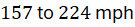 ) |
| Peak Water Hammer Impact Pressure |  to  (  ) |
Critical Roughness Threshold ( ) |  (turbulent boundary layer transition) |
| Elastomeric Coating Elongation at Break | 300% to 500% ultimate strain capacity |
| Annual Energy Production (AEP) Loss | 2% to 20% cumulative power reduction |
| Polyurethane Topcoat Thickness |  to  (  ) |
| Rain Erosion Resistance (revolutions) |  at simulated tip speed |
Maintenance, Repowering, and In-Field Repair Metrics
Addressing severe surface roughness degradation requires scheduled maintenance interventions, ranging from manual blade recoating using automated rope-access systems or specialized drone repair platforms to complete factory-refurbishment retrofits. Field repairs involve stripping eroded coating layers, sanding composite substrates to remove micro-cracks, and applying ultraviolet-curable polyurethane putty or erosion-resistant tape shields.
Quantifying erosion severity via optical scanning, photogrammetry, or ultrasonic non-destructive testing (NDT) enables operators to optimize repair schedules before structural reinforcement layers are compromised by moisture ingress and galvanic corrosion. Timely maintenance interventions restore aerodynamic profiles and recover lost annual energy production, preventing long-term structural failure of the composite blade shell.
The Final Take
Mastering wind turbine blade leading edge erosion aerodynamics establishes the crucial engineering framework required to preserve long-term energy yield and structural integrity. Citing IEA wind technology reports and fluid dynamics research, mitigating water hammer impact stress, controlling surface roughness transitions, and deploying high-durability polyurethane coatings minimizes aerodynamic drag penalties. By combining advanced composite protection with proactive maintenance scheduling, wind turbine blades sustain optimal power conversion efficiency across multi-decade operational lifespans.

Comments (0)
Login to leave a comment.
No comments yet. Be the first to share your thoughts!